


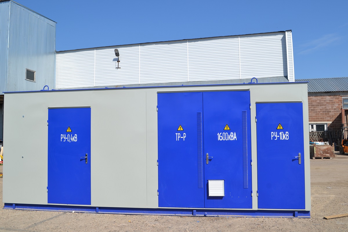
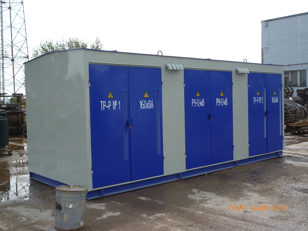
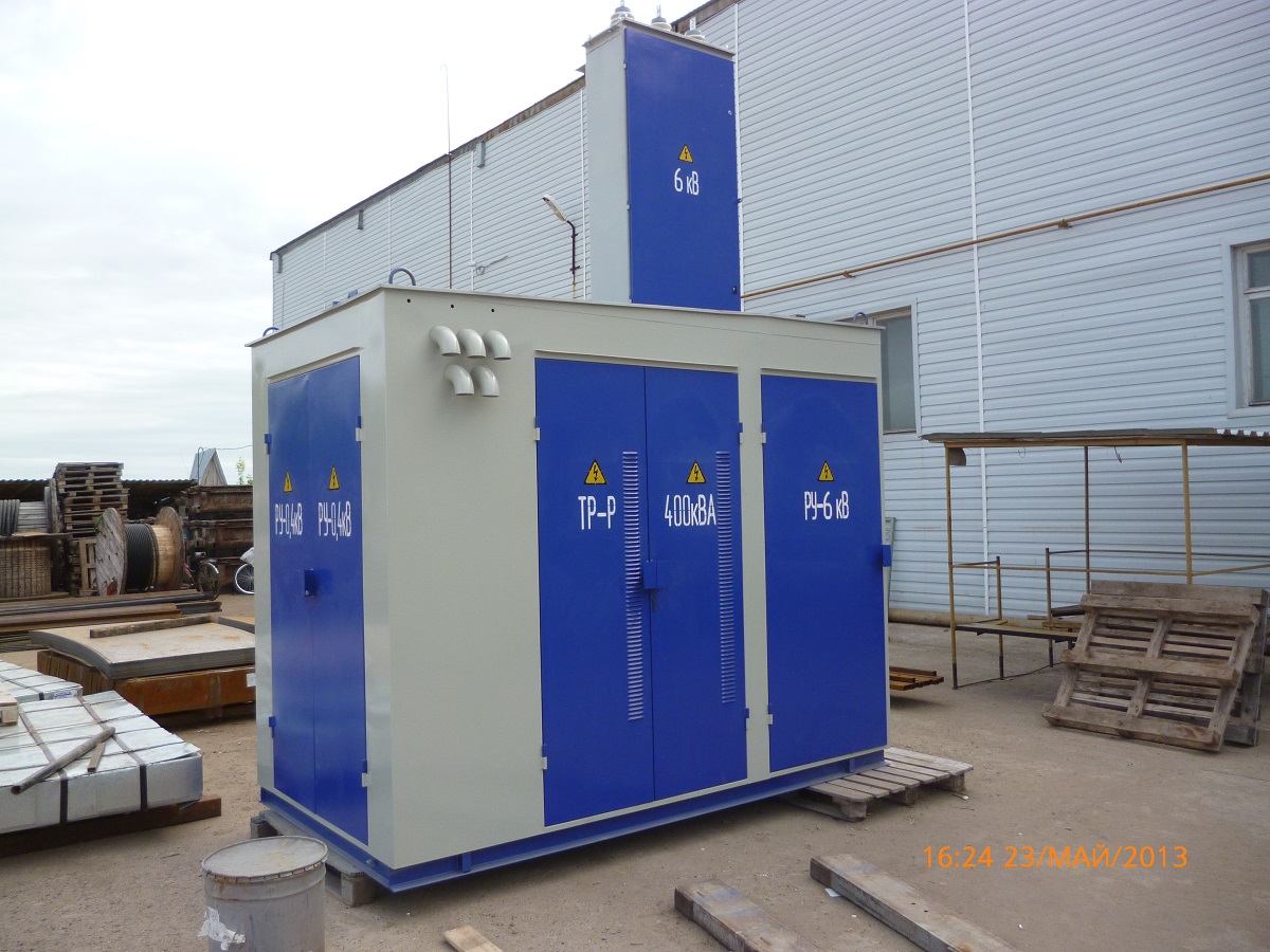
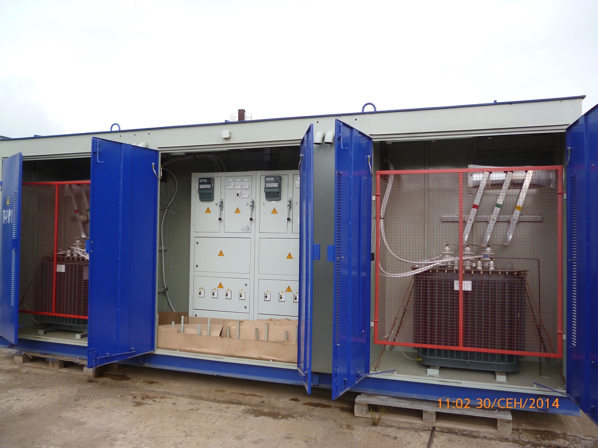
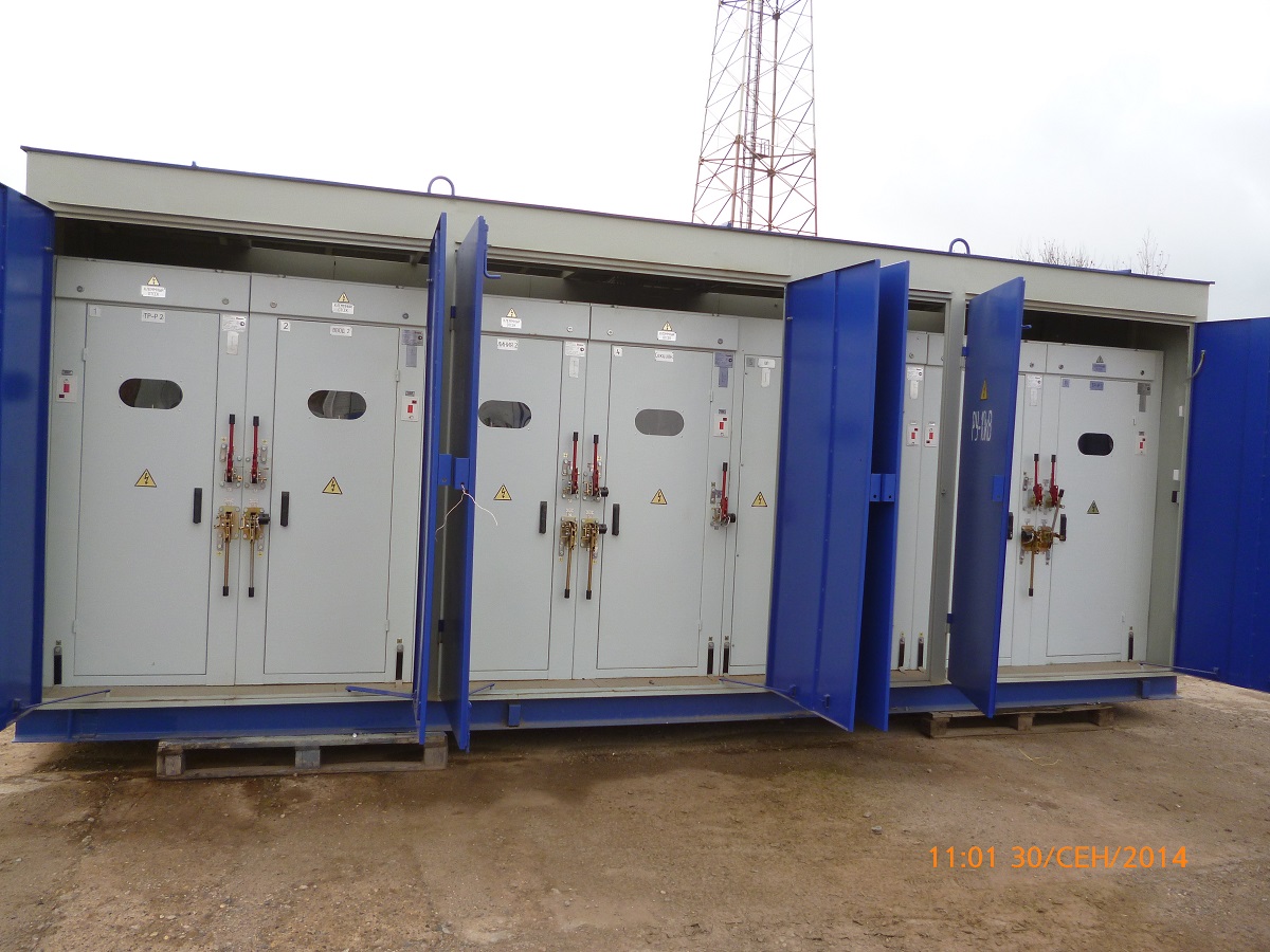
KTPK (PACKAGED TRANSFORMER SUBSTATION OF THE CABIN TYPE)
Description
The packaged transformer substations of the cabin type with the 6 or10 kV voltage (herein after KTPK) are designed for power supply of agricultural users, separate settlements and industrial facilities, construction operations and various industrial activities in areas with moderate or cold climate.
The KTPK substations can not be operated under the following conditions:
- under conditions of jolting, vibrations and impact effects;
- power infeed on the lowest voltage side;
- installation in explosion and fire hazardous areas according to the Electrical installation code and special environments according to GOST 24682-81.
Normal functioning of the substations is provided under the following conditions:
- installation altitude above the sea level – not more than 1000m;
- environment: industrial environment according to GOST 15150-69. Non-hazardous environment containing no reactive gases or vapors in concentrations that may deteriorate excessively the parameters of the KTPNU (RTPNU) substations.
Parameters
|
Parameter name |
Parameter value |
|
Power transformer capacity, kVA |
25; 40; 63; 100; 160; 250; 400; 630; 1000; 1250; 1600; 2500 |
|
Nominal voltage on the high-voltage side, kV |
6; 10 |
|
The highest operating voltage on the high-voltage side, kV |
7,2; 12 |
|
Nominal voltage on the low-voltage side, kV |
0,4 |
|
Short-time thermal current on the high-voltage side , kA |
20 |
|
Short time electrodynamic current on the high-voltage side , kA |
51 |
|
Input circuit insulation resistance on the high-voltage side , MOhm, min |
1000 |
Classification
|
Classification |
Version |
|
According to the type of the power transformer |
With an oil transformer; with a dry transformer |
|
According to the number of power transformers |
One; two o more transformers. |
|
According to the number of modules |
Single-module; multi-module |
|
According to the type of neutral terminal of the power transformer on the lowest voltage side |
Earth and neutral connected; with an insulated neutral (without a neutral bus) |
|
According to diagrams of connection to circuits |
Dead-end; through-type |
|
According to the phase-displacement group of power transformers |
Yн / D, Y / Yн, D / Yн |
|
According to the type of connection to voltage input devices and low voltage switchgears |
By means of cables; copper uninsulated busbars; Aluminum uninsulated busbars |
|
According to the type of the high-voltage terminal |
Air; cable |
|
According to the type of the low-voltage terminal |
Air; cable |
|
According to the types of automatic switches |
Fixed; plug-in type; Draw-out type |


No Comments